Disclaimer
I have no idea what I'm doing when it comes to PCB design. While I think my designs are suitable for what I want it to be, none of this should be seen as a tutorial or a starting-off point. In my haste to get a PCB designed and manufactured, I tried to jump right into the deep end and design Wheatley. Wheatley was not the first name I chose, though. A friend suggested "Bread," a play on Breadboard, and at first I liked the idea of naming different iterations of the computer different names of grain, though I ended up landing on Wheatley.
But I digress.
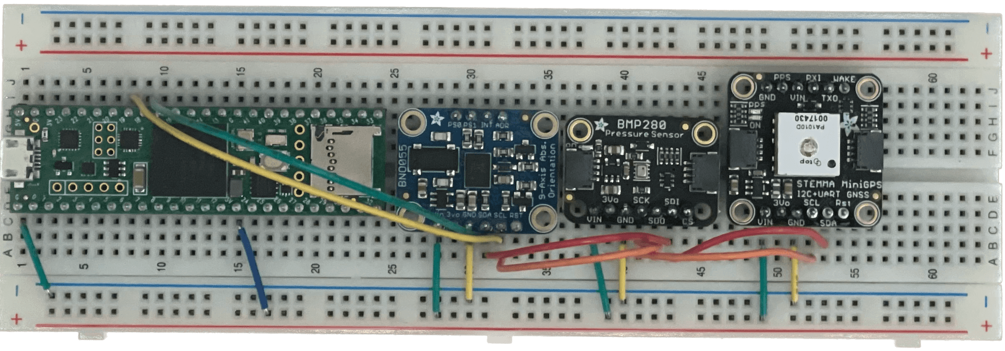
Version 0: Unnamed Breadboard Testbed

This board is for testing code on known-working hardware. Most, if not all, of my Control Theory is done on this board to eliminate variables and because it's very easy to see at-a-glance what orientation the code should think the board is in, versus reality. This does not allow me to plug 12V batteries to the board currently, but there are ways to do it, and it's plugged in via USB most of the time anyway for diagnostics over serial.
Version 1: Wheatley

Defining Sensors/Requirements
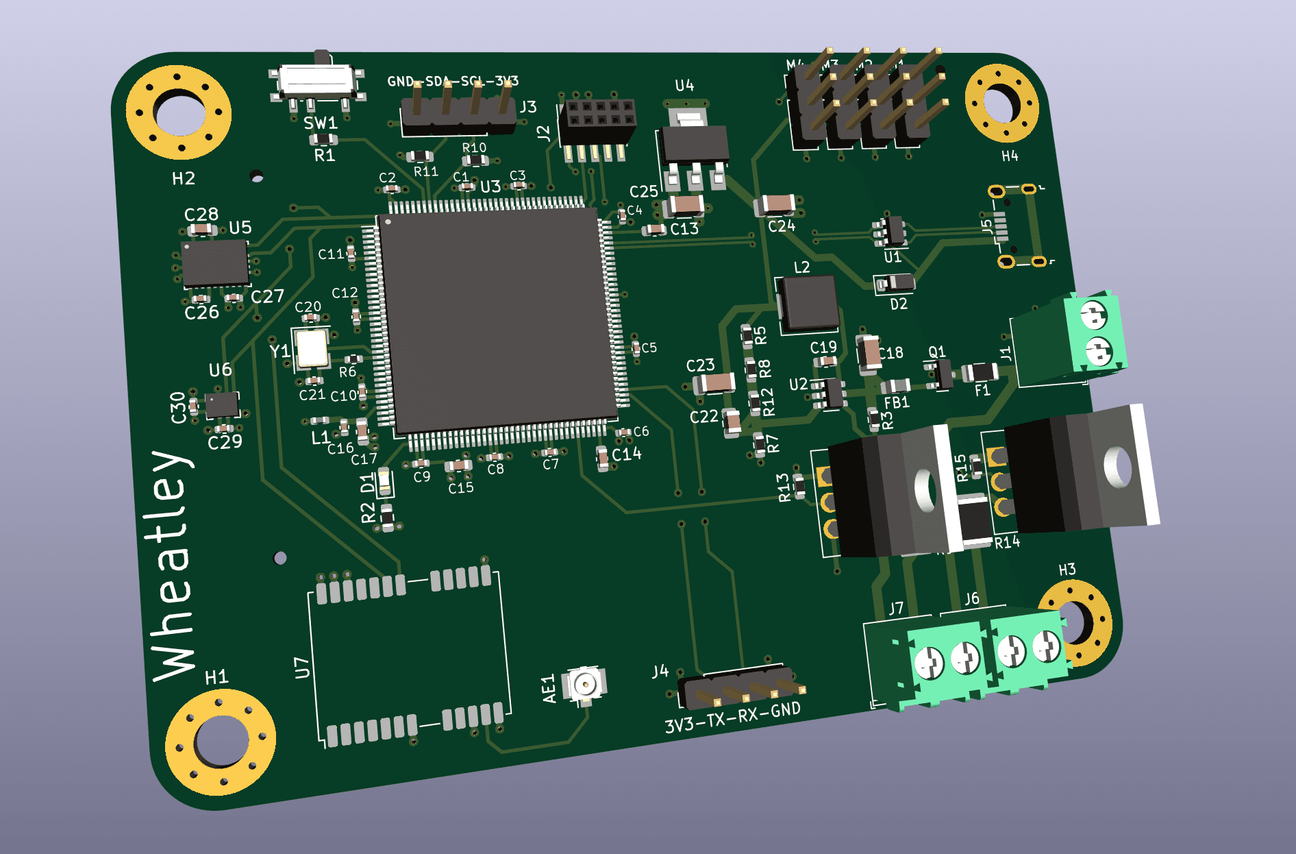
Wheatley is the first version of my flight computer. Wheatley is meant to be able to control any and all vehicles I put it in. Fixed-wing drones, fin-stabilized/thrust-vectored rockets, rotary craft, gliders, anything. I bit off much more than I could chew for this one. I did not expect it to be a seamless process, and I did not think it would work on the first go. As of time of writing, I have yet to order the PCB. Though I have the schematic and a general idea of the PCB layout. I will update this blog as soon as the PCB is ordered and the soldering is done. It was designed in Kicad, an open source CAD program for PCB design and manufacturing.
STM32H743ZIT6
My reasoning behind this processor is incredibly well-informed, thought-out, and came down to exactly the right processor for my use case. No other processor would have been sufficient in my goals.
Well, that isn't entirely true. My basic requirements for a processor were sufficient documentation and support for that processor, or at least the family of processors, and programability. I am a software engineer, anything I can do to make my life easier on the software side, I am going to do. I could not have designed this board without help from Phil's Lab on YouTube and most (if not all) of his content is centered around STM32. The reason I chose this specific processor was its performance (the H7 being among the high-performance family of STM32 processors) and that a popular dev board uses this exact processor. It would mean that I could purchase the board from a manufacturer and have, at least in theory, a 1:1 of my custom board to eliminate variables.
A third-ish reason is manufacturability. It's not a BGA which makes my life that much easier when it comes to building the PCB and doing any hand-soldering. Even some PCB fabs charge extra for BGA manufacture so I will avoid it as much as I can.
Bosch BNO055 (Accelerometer, Gyroscope, Magentometer, and Sensor-Fusion)
My experience with this sensor is not as much as others who have some very integrated and hyper-specialized code bases for it, but I can already tell it's going to do so much for me already. Aside from just getting the 9-DOF values, one of the big selling points for the sensor is the ability to grab the orientation in Quaternions directly. Rather than trying to derive the orientation from the different acceleration values combined with a little bit of trig, just use quaternions from the sensor directly. There's a real chance that the acceleration combined with some trig would have been used to generate quaternions to determine orientation anyway.
Calibrating the sensor is a bit of a pain, but that only needs to be done once on startup and it is calibrated for the rest of operation. Calibration involves flailing around the sensor and letting it rest until the magic rocks inside are happy. You can also query the temperature from the sensor, but it also gets quite hot during operation, so...I guess you could check to see if the board is on fire?
BMP280 (Barometric Pressure/Temperature)
I don't have a lot of explanation for this sensor other than it's a very popular, highly-supported, heavily-documented, and inexpensive sensor. It was popular when I started looking and wasn't too much, so I picked it. There might be better options out there, or less expensive options, but this is the one I chose when I set out to make a custom flight computer. It works just fine, and is another data point to determine the altitude and position of an air vehicle when combined with other sensors.
NEO-M9N (GPS)
I don't have a specific reason for using this radio other than it communicates over I2C which is far better than the sea of serial radios.
The Schematic (PDF Here)

The schematic for Wheatley was done in a FOSS program called KiCad. My reasoning for using it was because of how well documented and supported it is, and that Phil's Lab utilizes it pretty extensively. I had originally been using EAGLE, but made the transition when it was announced that EAGLE would no longer be getting support and instead, users were to switch over to the subscription service bundled with Fusion360. This saddened me deeply.
The board is powered by 1 of 2 options. Firstly, you could plug in a battery which delivers 12V to a DC-DC buck converter circuit that steps down the voltage to 5V. This 5V rail powers the servo/stepper motors. It also goes into a linear regulator that outputs 3.3V onto a power plane on the board. I chose to use a linear regulator between the 5V and 3.3V rails because of the lack of complexity and the lack of heat generation compared to, say, 12V to 3.3V across a linear regulator. It was much more simple than adding another buck regulator circuit as well, and cuts down on cost. The other option is to plug in a USB Micro, which delivers 5V to the same 5V rail. What this means is that the servo/stepper motors can be powered, but anything on the 12V rail will not have any power. I see this as a plus, even if it is a side effect. If the computer is plugged into the board, the pyro channels can't ignite. This is a complete win.
The sensors communicate primarily over I2C as shown in the schematic. While something like SPI would have been quicker, it uses far more pins on the STM32, is a touch more complex, and not all the sensors support communication over SPI. I plan to work around this with threads or multitasking through RTOS. Other board designs I've seen utilize multiple processors but that just sounds like a nightmare and I wanted to avoid that at all costs.
Currently the board supports 4 stepper motors, 2 pyro channels, and outputs for UART and, again, I2C through pin headers.
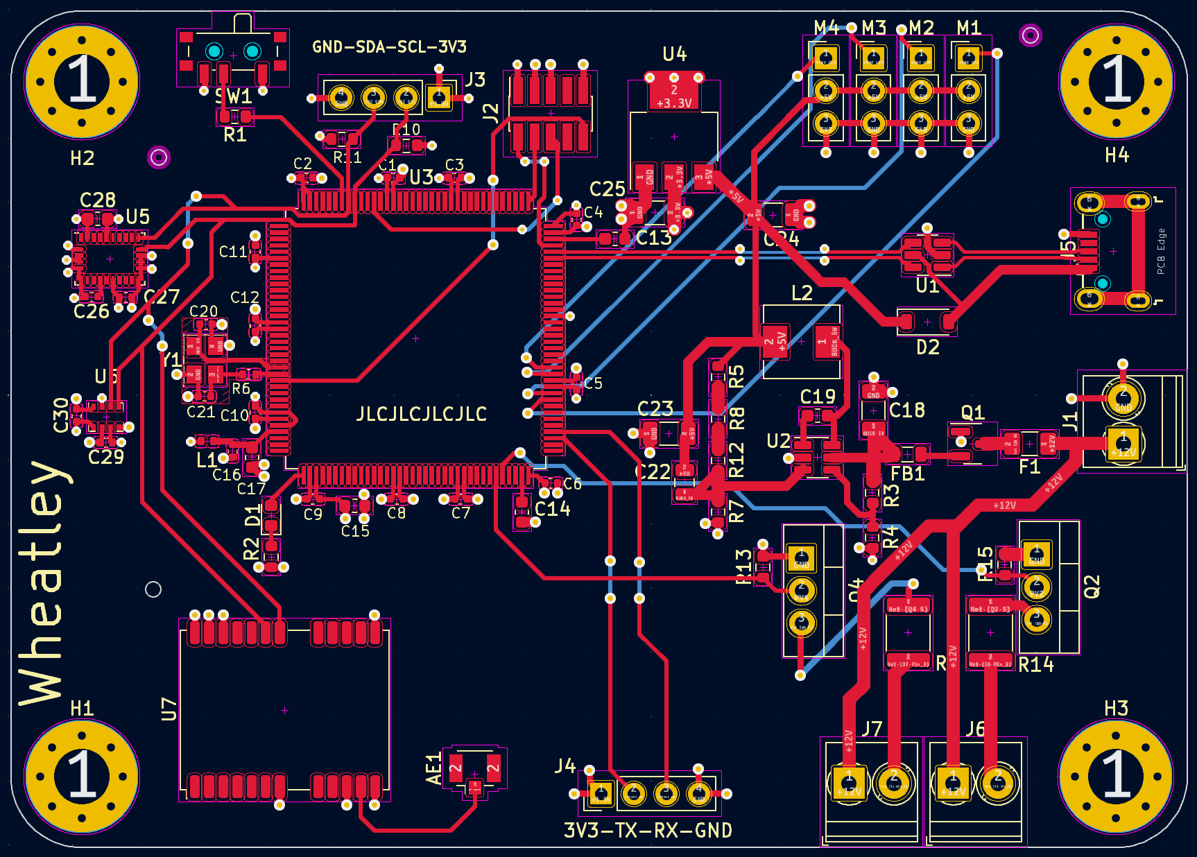
The PCB (PDF Here)

This part of the design process was easily the most difficult for me and took the most research. It was very easy to just label a cap as 100nF, for example, but to actually find one in the size designated in stock took quite a bit of effort. Rinse and repeat for every inductor, resistor, MOSFET, etc. Another difficulty was learning about differential pairs, such as USB positive and negative. Thankfully, KiCad has builtin support for differential pairs, but that took quite a bit of fussing with the location of the USB port, the reverse polarity protection, and the final traces to the STM32. Another thing I had to keep in mind was trace width and heat dissipation. I guarantee there are locations on this board that are sub-optimal for temperature and crosstalk, but that's part of the learning process. This is my first go at a PCB and I at least made something that I can experiment with. If it's a failure, I will just make a revision 2 based on the results of the first revision.